Welcome Aboard!

These pages will cover the restoration and upgrades I have done to a 1979 Choate 40.
I acquired the vessel in poor condition at a reasonable price and so far have put twice that amount into her.
From the evidence I have found, she had been de-masted, run aground several times, slightly flooded, run hard and put away wet.
Fortunately, she had new standing rig with a used mast from a Catalina 40 and a recent head job on the motor.
The rest of the info I'll segregate into pages for detailed information.

Tuesday, April 2, 2013

Adding a Second Fuel Tank

I really don't like the idea of carrying jerry cans up on deck. I've already lost the vent cap of of one that I had from the jib sheets hitting it.  But if need be I can still add some if I had to. I may carry a couple empties just in case I need to go ashore for fuel.
These large empty voids behind the settees are a handy place for tanks except for their shape. The water tanks I had to jury rig but this fuel tank I was able to design it to fill the shape of the space w/o a lot of odd shaped voids around it. But did allow for some air space to help prevent moisture build up in the tank.
Here's the void, much like the for the water tank but the opposite.

A temporary support for measurements..................

 Templates for forward and aft end plates...............

Then the finished tank itself........................ Top.

The hull side..........................

You can see the taper of the hull here....................

 Stringers for tank support..................


Tank mounted in place.................

 The feed and return lines going down to the lower tank system.

Here's the lower (main) tank. The hoses come into the upper LH corner.


The vent is T-ed into the upper tank and on to the transom. The original vent line was clear plastic tubing. During the last survey I would have been hit on it but I told him it was being replaced soon with this additional tank install. So he let it go on the report.

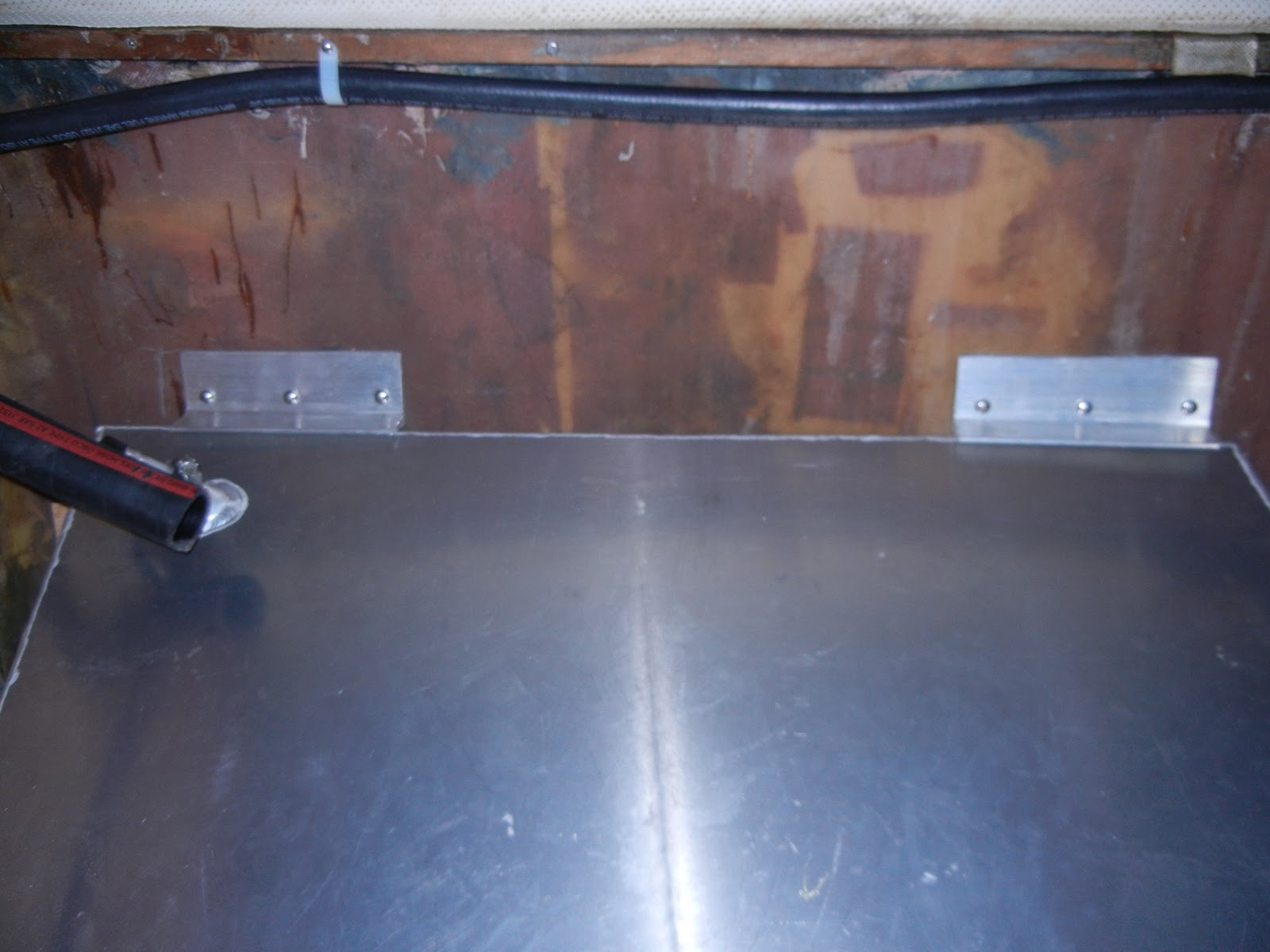
More support brackets to hold tank in place.
Getting the fill tube and vent lines in place was a real challenge.

 I had to cut a 45º hole up thru the lower corner of the chart table and then up under the nav station to the deck behind.
I could have run the fill line straight up but it would have been visible, and in the way of storage. I chose to sacrifice the far corner of the chart table.

The vent line ran between to panels. This one below and the bottom of the chart tables bottom half.

So, I had to cut an access hole to get the vent line up and out from between the layers.

Vent line running all the way aft and out the port side.

The new vent fitting on the outside.
Originally, the new vent fitting had a rubber washer, which was supposed to seal it, NOT!  That rubber would only last a couple years and the the thing would be leaking rain water inside. So, I cut off the rubber and added a SS flat washer and sealed it with 3M-4200.

Here is the old vent from long ago built. It's no wonder why my tank was taking so long to fill, it only was for a 1/2" hose with a 1/4" exit hole, and it had a piece of Scotchbrite stuffed in it. I suppose to keep out the bugs. The USCG reg's calls for a 5/8" certified hose, which it is now!

 The hole in the deck next to the other deck fill. I sealed up the balsa core and screw holes with epoxy filler & letting it cure before installing the deck fitting.


With deck fittings installed...............

 A side view of the tank installed with hoses and wiring.

Since I'm going to be storing gear on top of the tank, I added the fence board to protect the hose and wire fittings.


While working on the plumbing for the new tank I noticed the main (lower) tanks was moving a bit and since I needed to get in a tight spot next to the tank I decided to pull it out. It's a good thing! The blocks that I assumed were holding it in place were only held in by (4) #8 screws, which were only screwed into the 7/16" plywood below. And once I removed the tank I could wiggle the support blocks side to side.

Plus the screws were tight in the block and not the decking below. IAW not predrilled for clearance.

So, I enlarged the screw holes in the blocks and epoxied them to the deck then replaced the screws drawing them tight to the deck.  As well, I epoxied gussets on both sides of the blocks.

While is was still wet I tabbed in over the gussets up to the top of the blocks with two layers of fiberglass.

After all night curing, the rough edges were sanded so there would be no surprises if I needed to stick my hands down there, Ouch! As well, all the surrounding bulkhead edges were tabbed in to keep any possibel diesel leaks from reaching the bilges.

And a fresh coat of bilge paint for EZ clean up, if need be.

Now the tank is all in a plumbed up.....................

The electric fuel pump is only designed to pump from the main tank. But it's only for changing filters and bleeding the lines if need be.


Here's the directional valves for switching from the auxiliary to the main tank.

The directional valve for the electric pump, or tanks. It's only set up to pump from the main tank, otherwise I'd have to install another 3-way valve.


  Here's the access cover to the valves...............


Took the boat out on Wed. 4/24/13 and all worked fine. I just have to make sure when the fuel nozzle clicks off to stop filling the tanks or it could come out the vent fitting.


Thursday, January 10, 2013

Installing a Watermaker

I haven't really put much personal info in here. It's been more like a documentation of work. Basically it is, but, I think I'l break the monotony a little.

I'm working on taking this vessel to the S. Pacific.  So, a lot of the work/upgrading is based on the tropical climate. I need a vessel that can take strong force winds and be efficient for it's size. And I want a vessel that doesn't leak from top or bottom. I don't mind living in high humidity, but I don't want a swamp under me either. So one of the last internal items to be added is this; Installing a Watermaker.

I would have liked to have a Spectra 200T or Cape Horn due to it's shorter run times in relation to amps. But a couple items makes it unfeasible. The size of the compartment available is just a little too short for the C.H.  As well, the 200T needs to be in warmer waters (>50º F) due to it's pressure. I could have dealt with that buy extremely conserving water until I got farther south before starting up the system. Like maybe Oregon/Cal. border.  But I'd also like to see this thing work before heading off.  So, I'll be going with the Deluxe 150 unit.

Here's the space that it's going into. On the right are two 17 gl. tanks that have been in the vessel, since I acquired it. They are nice and clean. They've only had tap water in them as far as I know.

A closer view. The thruhull on the left is the waste outlet from the head.  It's nice and clean, no smell!

And behind the seat I'm installing an additional 25 gl. water tank.

Here, behind the seat is a nice void where I can install an extra water tank. It's a leaning "V" shape with a little radius from top to bottom, which turned out to be a 63" radius.   Also, it tapers forward (to the left). This is the Stbd side amidship.

After selecting the tank, this is the board size that needs to carry the footprint of the tank.

Here are drawings of the hull shape viewed from top to bottom......

and then fore & aft.  I selected about 4 tanks from a dealer that are pre-made. And then cut out to scale patterns the shape of each tank and tried fitting each into the drawing. I couldn't find anyone to make a custom tank to fit the hull shape.

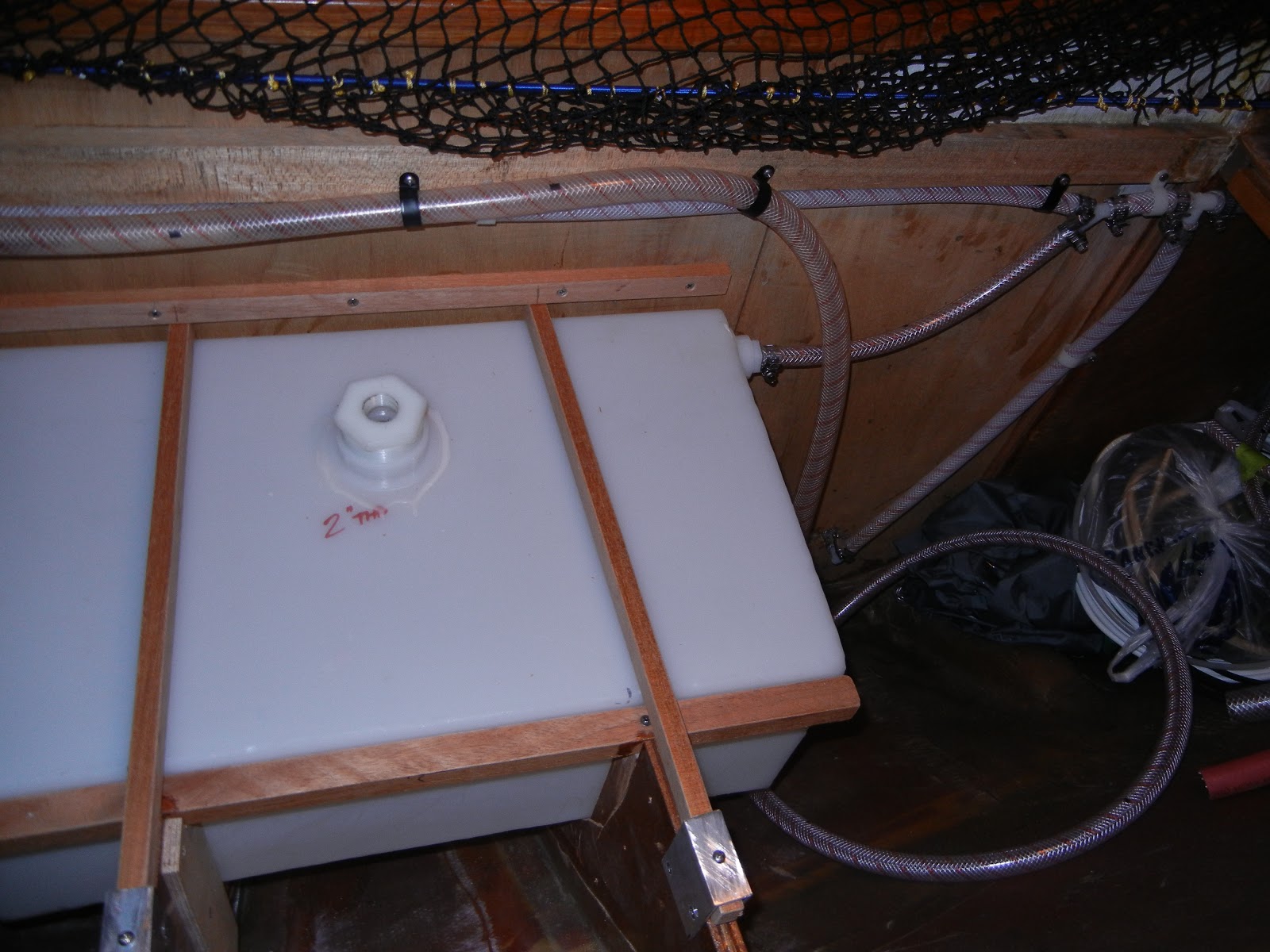
Here's the tank that I selected. It only fills about half of the space. Had the fittings installed per my instruction. And selected it with two 3/4" pipe fittings on the end and a 2" pipe on top surface. The bottom fitting is for the water-out line. The top 3/4" fitting is for the vent. And the 2" top surface fitting it for a 2" inspection cap and fill-line.

The bottom support is screwed to the bulkhead and tabbed to the hull, to allow flexing on the hull side.

Those forms are cut to support the tank. It's not a perfect match but I'll shim later to support gaps.

Here, the forms partly tabbed in place and wait to cure.

Notched and also added a cross wood it help with support. This is a 25 gl. tank, which weighs in at about 208 lb. So every bit of support will keep it from moving around in a rough sea.

The braces fully tabbed in place. I had to cut away part of the upright edge to get the tank out. A little fault that I had planned for, but forgot, being anxious to get it in. This tank took 3 weeks form start to finish to get in.

Here, the tank fully installed. I sistered in the upright edge and made some brackets to hold the tank down. There are also a couple blocks each on the bulkhead and base to keep the tank from moving.

Now I need to order the Spectra and install it in this space! The white board is a bilge access cover.

More to come after the watermaker arrives. ;-)
It's here, 2/9/13 ............................

And it all fits in with room to spare.

The mounting board epoxied and screwed in place.


Pump in place................................


 All the other pieces mounted in place

A couple steps back for better view...................................

Starting the plumbing.................................

 Here everything mounted with the added product valves for duel tanks.

Here the plumbing to the upper/outboard tank #3 and over board discharge, which it T'ed into a bilge pump line. I doubt I'll be making water if the bilge pump EVER comes on.

Here's all the the piping installed, except the thruhull for the inlet line, which I'll install in the spring durning the haul out.  I heard it was difficult to install water makers but don't know why. Pretty simple to me!

 A view looking aft over the #1 & #2 tanks. They are mis-marked here but the aft tank is now the #2. There is a valve next to the #2 tank that I shut off to isolate #2 from #3. With the valve open the #3 will gravity flow into the #2 tank. This saves having to add another hose and valve under the sink.

A couple views with the settee cover on.....................


And with the lids in place...........................

And then of course the thruhull fitting...... On the inside the bilge was so shallow that I had to custom make a seacock fitting (street elbow) so that it would fit under the deck. Pictures later.