I really don't like the idea of carrying jerry cans up on deck. I've already lost the vent cap of of one that I had from the jib sheets hitting it. But if need be I can still add some if I had to. I may carry a couple empties just in case I need to go ashore for fuel.
These large empty voids behind the settees are a handy place for tanks except for their shape. The water tanks I had to jury rig but this fuel tank I was able to design it to fill the shape of the space w/o a lot of odd shaped voids around it. But did allow for some air space to help prevent moisture build up in the tank.
Here's the void, much like the for the water tank but the opposite.
A temporary support for measurements..................
Templates for forward and aft end plates...............
Then the finished tank itself........................ Top.
The hull side..........................
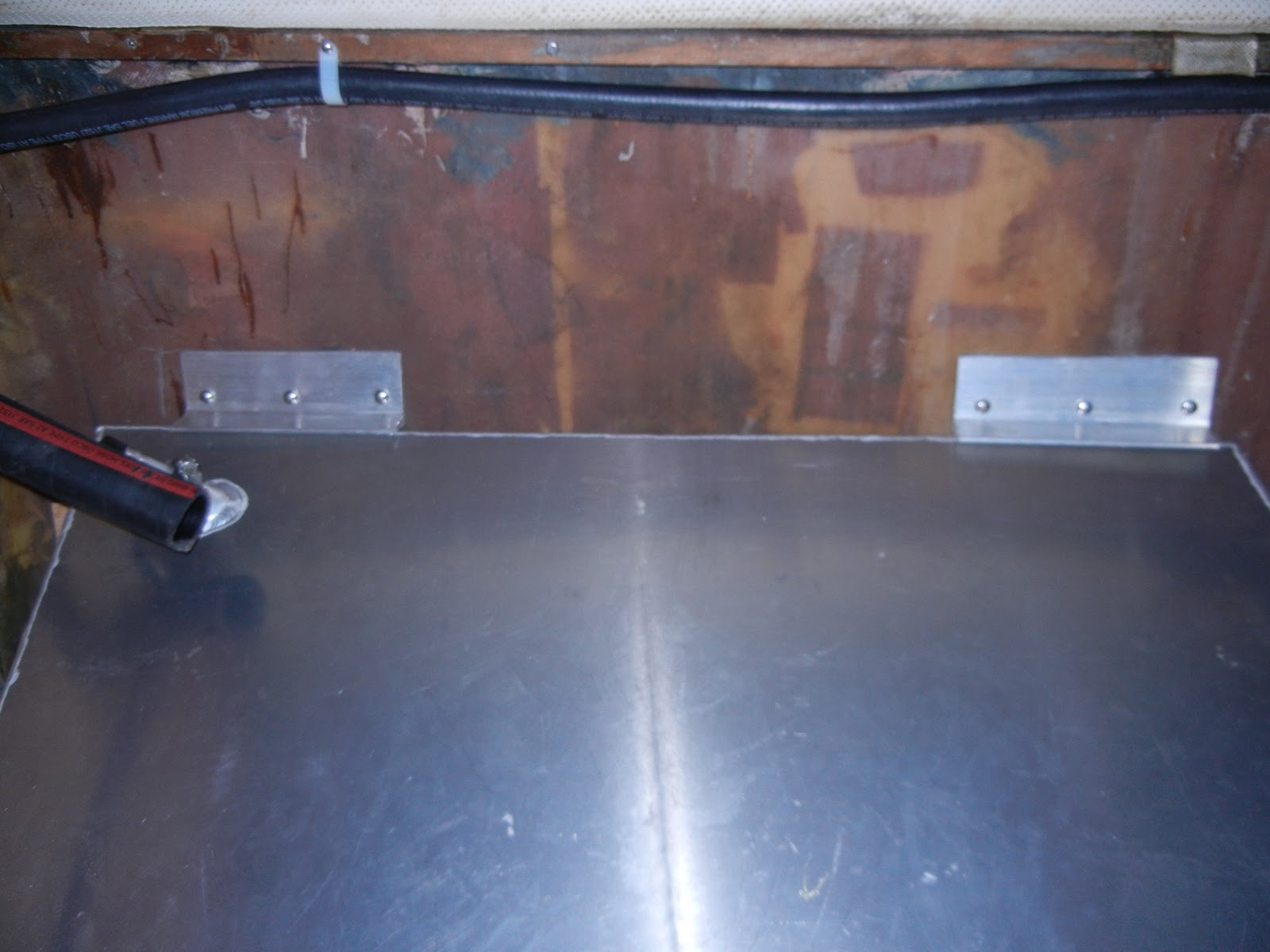
You can see the taper of the hull here....................
Stringers for tank support..................
Tank mounted in place.................
The feed and return lines going down to the lower tank system.
Here's the lower (main) tank. The hoses come into the upper LH corner.
The vent is T-ed into the upper tank and on to the transom. The original vent line was clear plastic tubing. During the last survey I would have been hit on it but I told him it was being replaced soon with this additional tank install. So he let it go on the report.
More support brackets to hold tank in place.
Getting the fill tube and vent lines in place was a real challenge.
I had to cut a 45º hole up thru the lower corner of the chart table and then up under the nav station to the deck behind.
I could have run the fill line straight up but it would have been visible, and in the way of storage. I chose to sacrifice the far corner of the chart table.
The vent line ran between to panels. This one below and the bottom of the chart tables bottom half.
So, I had to cut an access hole to get the vent line up and out from between the layers.
Vent line running all the way aft and out the port side.
The new vent fitting on the outside.
Originally, the new vent fitting had a rubber washer, which was supposed to seal it, NOT! That rubber would only last a couple years and the the thing would be leaking rain water inside. So, I cut off the rubber and added a SS flat washer and sealed it with 3M-4200.
Here is the old vent from long ago built. It's no wonder why my tank was taking so long to fill, it only was for a 1/2" hose with a 1/4" exit hole, and it had a piece of Scotchbrite stuffed in it. I suppose to keep out the bugs. The USCG reg's calls for a 5/8" certified hose, which it is now!
The hole in the deck next to the other deck fill. I sealed up the balsa core and screw holes with epoxy filler & letting it cure before installing the deck fitting.
With deck fittings installed...............
A side view of the tank installed with hoses and wiring.
Since I'm going to be storing gear on top of the tank, I added the fence board to protect the hose and wire fittings.
While working on the plumbing for the new tank I noticed the main (lower) tanks was moving a bit and since I needed to get in a tight spot next to the tank I decided to pull it out. It's a good thing! The blocks that I assumed were holding it in place were only held in by (4) #8 screws, which were only screwed into the 7/16" plywood below. And once I removed the tank I could wiggle the support blocks side to side.
Plus the screws were tight in the block and not the decking below. IAW not predrilled for clearance.
So, I enlarged the screw holes in the blocks and epoxied them to the deck then replaced the screws drawing them tight to the deck. As well, I epoxied gussets on both sides of the blocks.
While is was still wet I tabbed in over the gussets up to the top of the blocks with two layers of fiberglass.
After all night curing, the rough edges were sanded so there would be no surprises if I needed to stick my hands down there, Ouch! As well, all the surrounding bulkhead edges were tabbed in to keep any possibel diesel leaks from reaching the bilges.
And a fresh coat of bilge paint for EZ clean up, if need be.
Now the tank is all in a plumbed up.....................
The electric fuel pump is only designed to pump from the main tank. But it's only for changing filters and bleeding the lines if need be.
Here's the directional valves for switching from the auxiliary to the main tank.
The directional valve for the electric pump, or tanks. It's only set up to pump from the main tank, otherwise I'd have to install another 3-way valve.
Here's the access cover to the valves...............
Took the boat out on Wed. 4/24/13 and all worked fine. I just have to make sure when the fuel nozzle clicks off to stop filling the tanks or it could come out the vent fitting.